Filament calibration is the difference between a part that measures correctly and one that looks close enough. This guide covers the five FDM calibration routines in order — pressure advance, flow rate, temperature tower, retraction and max volumetric flow — and what to do with each result.
Run these calibrations for every filament you use, and again for every nozzle type (different nozzle sizes and nozzle materials). Values dialed in for one filament or nozzle do not carry over to another, so save your results in a separate filament preset for each filament and nozzle combination. Nozzle size calibration matters as much as the material: a 0.4 mm and a 0.8 mm nozzle will not share values.
What is shown here
The screenshots use CreatWare on a CreatBot D400 HS with a 0.6 mm nozzle running ASA-GF, but the same five routines appear in most modern slicers. Every spool in the Rev1 filament range lists its recommended temperature range on the label, which is the starting point for step 3. Calibrating a new machine? The FDM printer range is here.
In this guide
1. Pressure Advance
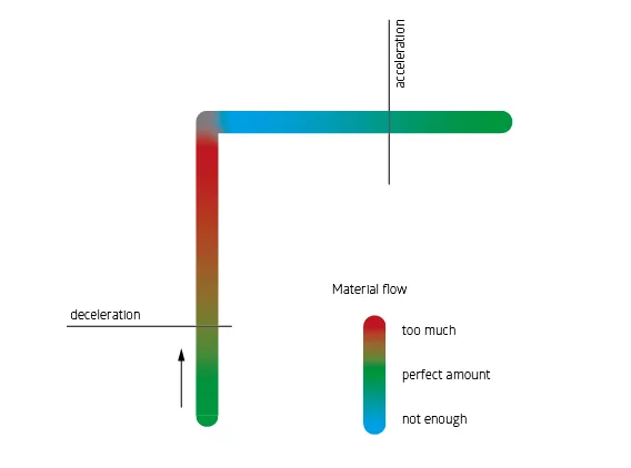
What pressure advance is: the setting adjusts extrusion during acceleration and deceleration — more filament out during acceleration, less during deceleration of the tool head. Adjust it for every filament and every nozzle size.
- Create a new project within your slicer.
- In the upper right-hand corner, use the calibration drop-down and select Pressure advance.
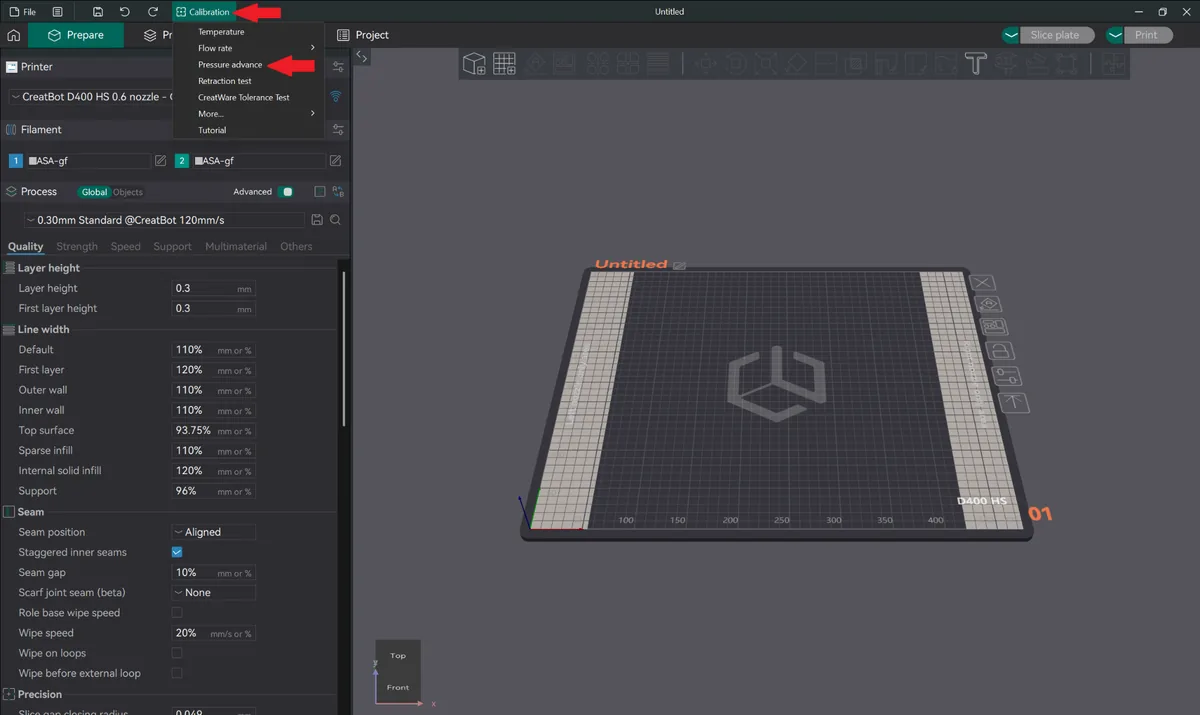
CreatWare calibration menu open on a CreatBot D400 HS with Pressure advance highlighted - Select DDE and PA pattern, keep the steps the same, and for acceleration and speed use your default outer wall acceleration and speed.
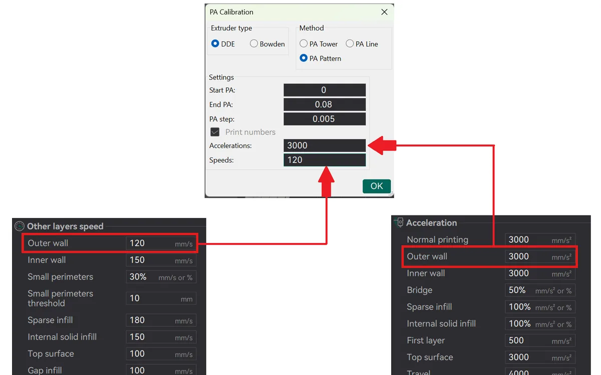
PA Calibration dialog set to DDE extruder and PA Pattern with acceleration 3000 and speed 120 matched to outer wall settings - Press OK and slice the calibration print. The model does not appear until the project is sliced.
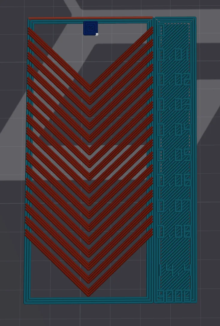
Sliced pressure advance chevron test pattern with numbered PA values - Run the print and inspect the results.
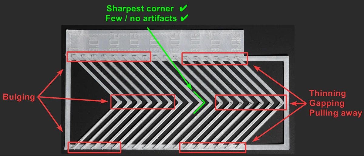
Printed pressure advance pattern annotated with bulging, thinning and the sharpest corner - Set the pressure advance value according to the best corner, in the filament settings.
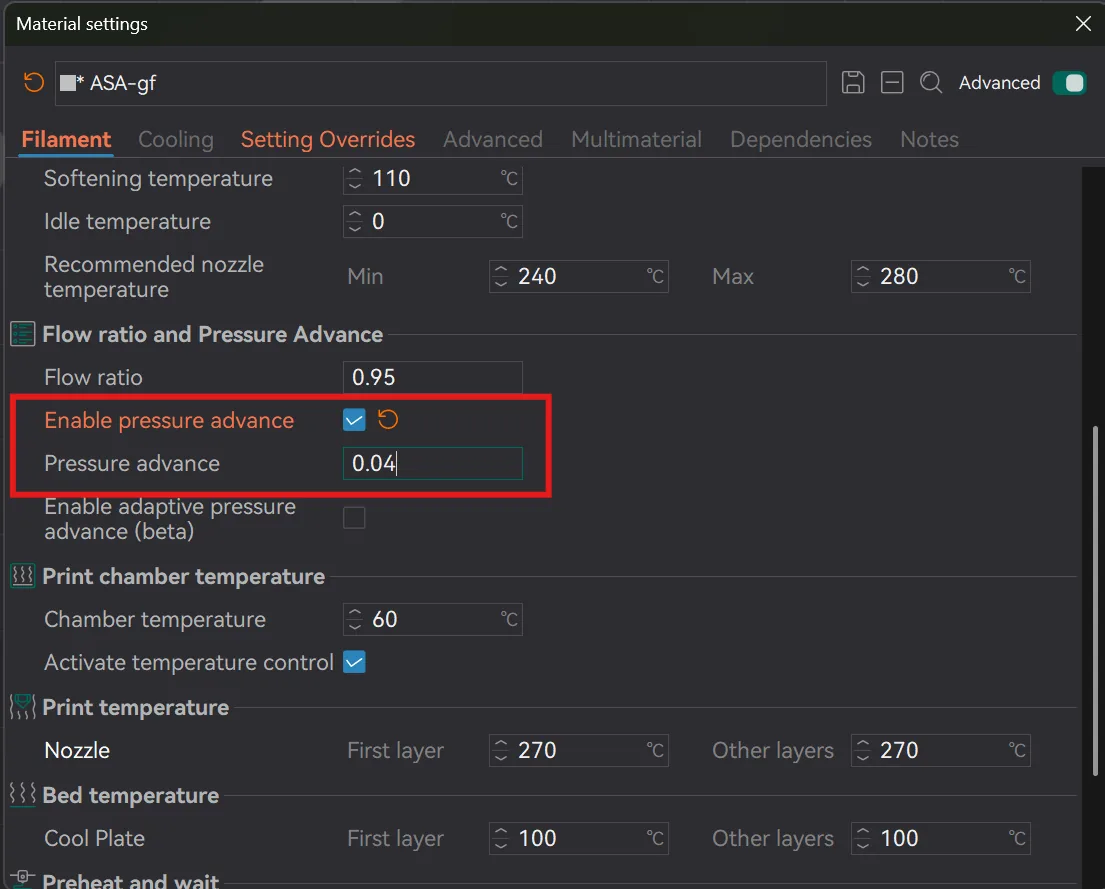
Pressure advance value 0.04 entered in the filament material settings
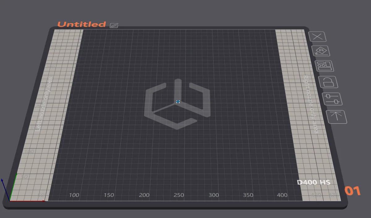
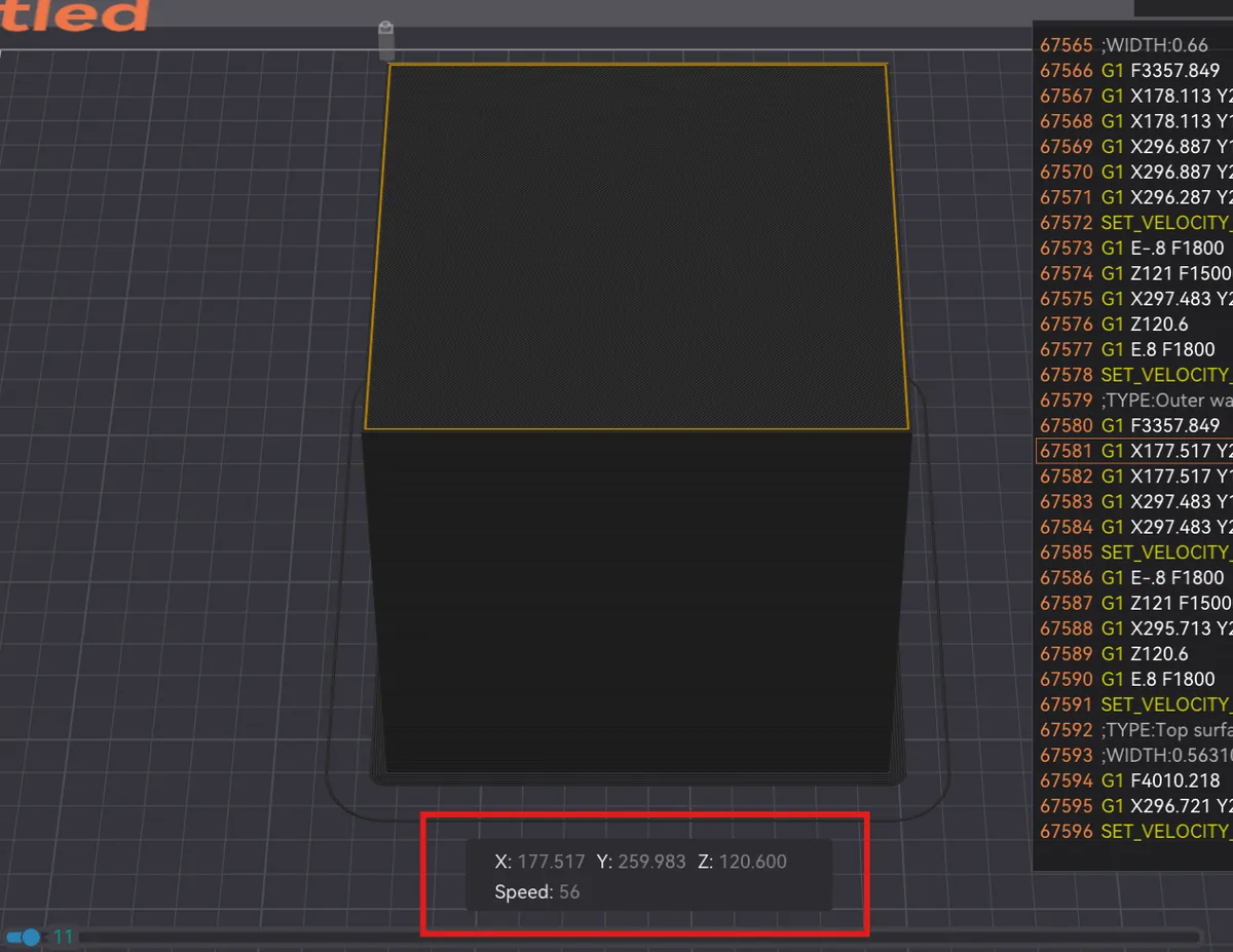
If your max flow rate came out low (for example Q = 10 mm³/s), add a scaled-up cube to an empty bed plate, slice it, and use the slider to read the real outer wall speed. Speed is always capped by the filament's max flow rate, so a 200 mm/s outer wall default may never be reached — here it tops out at 56 mm/s.
2. Flow Rate
Flow rate: the amount of filament pushed through the nozzle over time.
- Create a new project within your slicer.
- In the upper right-hand corner, use the calibration drop-down, select Flow Rate, then YOLO (Recommended).
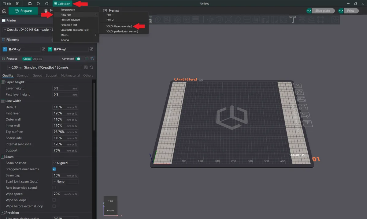
CreatWare calibration menu with Flow rate and YOLO Recommended selected - Slice and print the part.
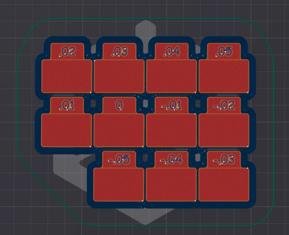
Sliced flow rate YOLO test showing eleven numbered tabs from .05 to -.05 - Inspect the print results and pick the best result tab.
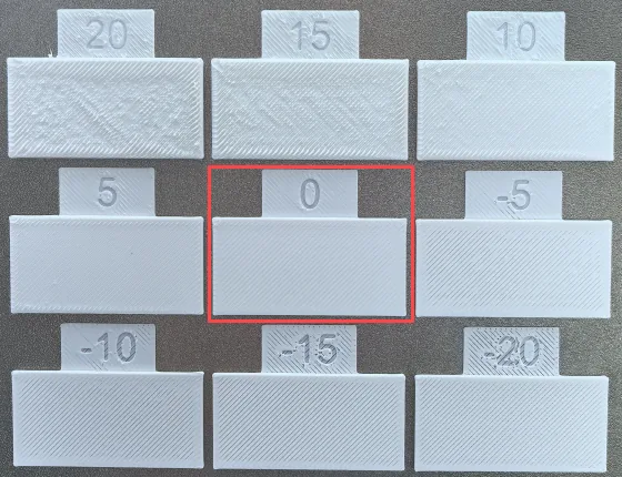
Printed flow rate tabs with the 0 tab marked as the best surface finish - Add or subtract the value on that tab from the default flow ratio.
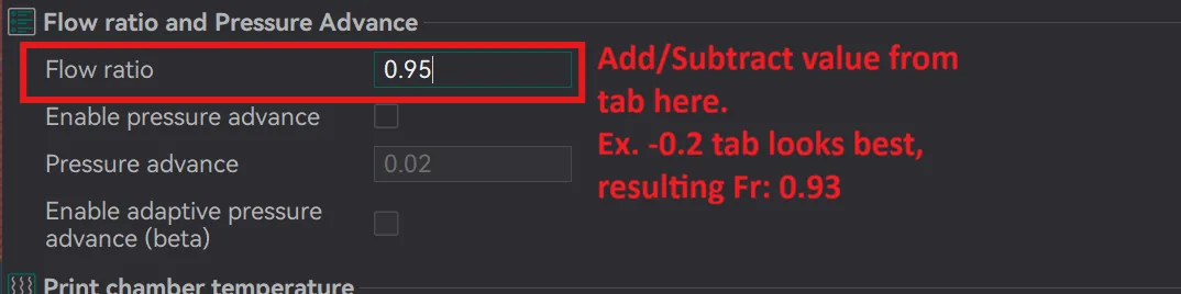
Flow ratio field in filament settings showing how to add or subtract the chosen tab value
3. Temperature Tower
- Create a new project within your slicer.
- In the upper right-hand corner, use the calibration drop-down and select Temperature.
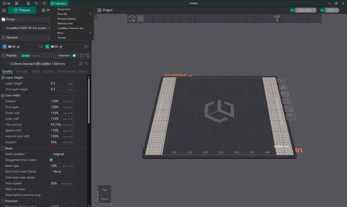
CreatWare calibration menu with Temperature selected - Input the temperature range found on the spool, or select the current filament and use its preset temperature range.
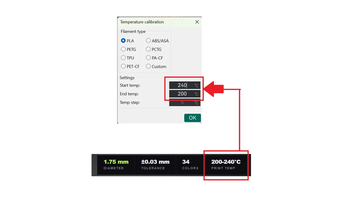
Temperature calibration dialog with start and end temperature taken from the 200 to 240 C spool label - Slice the print. Temp steps are locked at 5 °C, so the wider your range the taller the tower.
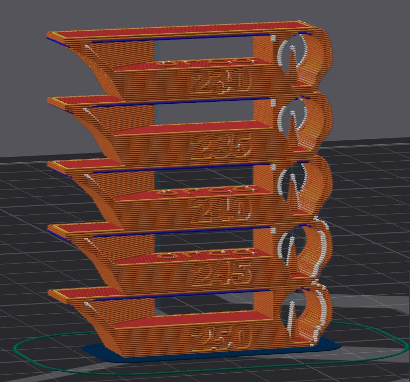
Close-up of the sliced temperature tower layers showing overhang, bridging and hole geometry 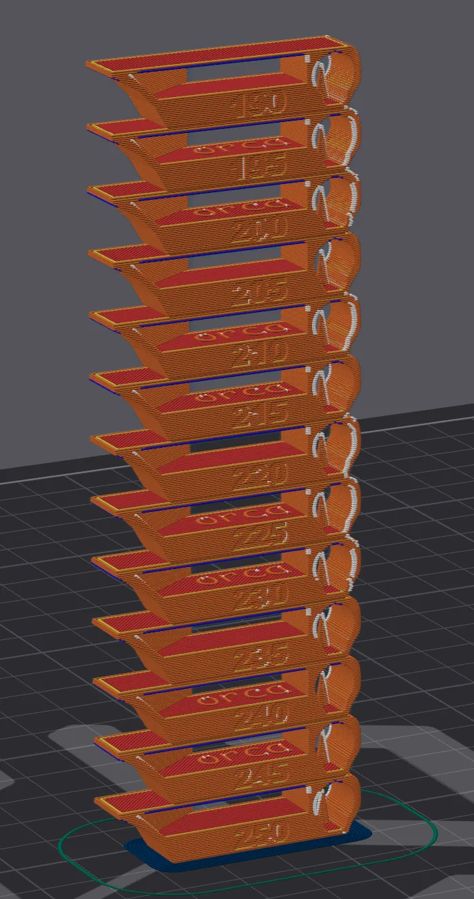
Full sliced temperature tower stepping from 190 C to 250 C in 5 degree increments - Print the tower and analyse the results.
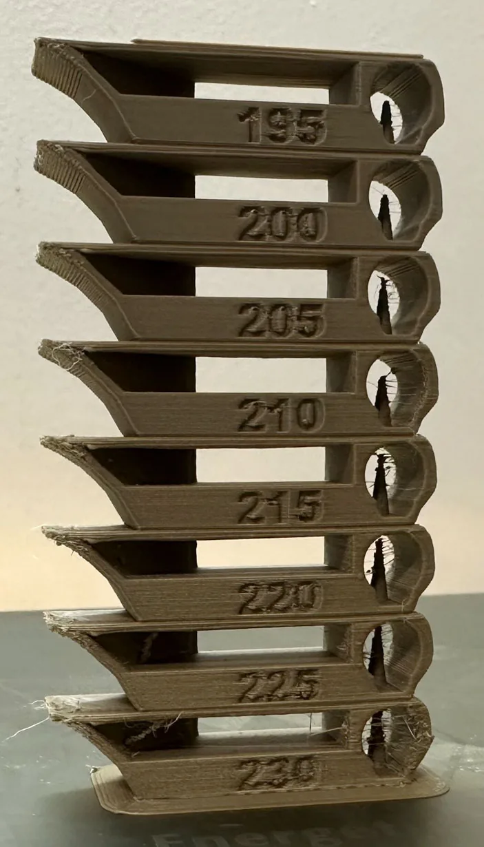
Printed temperature tower from 195 C to 230 C showing stringing differences between layers - Input the chosen filament temperature.
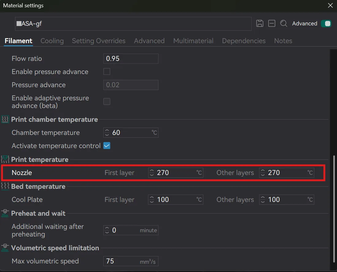
Chosen nozzle temperature entered in the filament print temperature settings
Each layer combines several geometries — overhangs, bridging, top shell, text, cone and hole. Inspect every layer and pick the best. Always go with a higher temperature layer if unsure.
Spool ranges differ sharply by polymer: a PLA tower sits far below a high-temp engineering filament, so re-run this whenever you change material family across the material range.
4. Retraction Test
Retraction: the slight pull-back of filament that prevents oozing and stringing while the tool head travels.
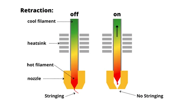
- Create a new project within your slicer.
- In the upper right-hand corner, use the calibration drop-down and select Retraction.
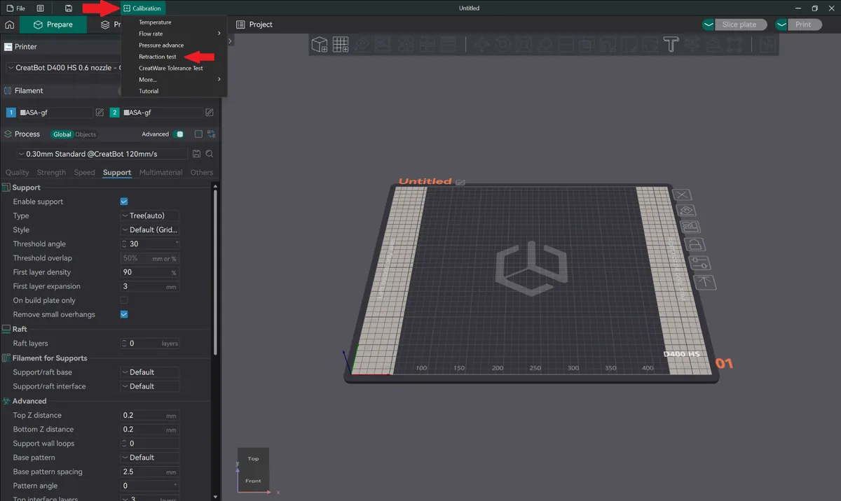
CreatWare calibration menu with Retraction test selected - Leave the values at default and press OK. Increasing the step distance shortens print time but is not recommended.
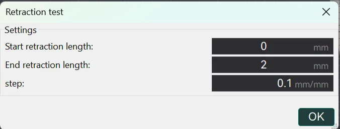
Retraction test dialog with start 0 mm, end 2 mm and 0.1 mm step left at default - Slice and print.
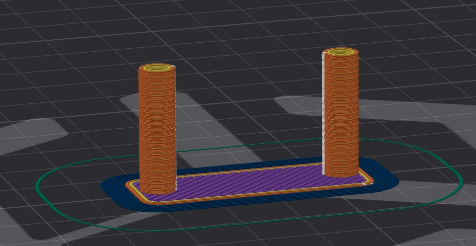
Sliced retraction test showing the twin towers the tool head travels between - Analyse the print, looking for the first rings with no stringing or oozing.
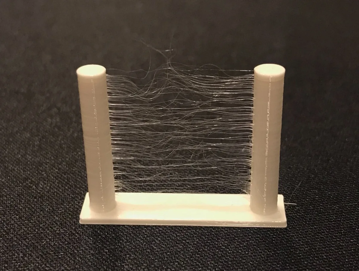
Printed retraction test towers covered in fine stringing between the posts - Use the slider and G-code preview to find the retraction length used for your chosen ring.
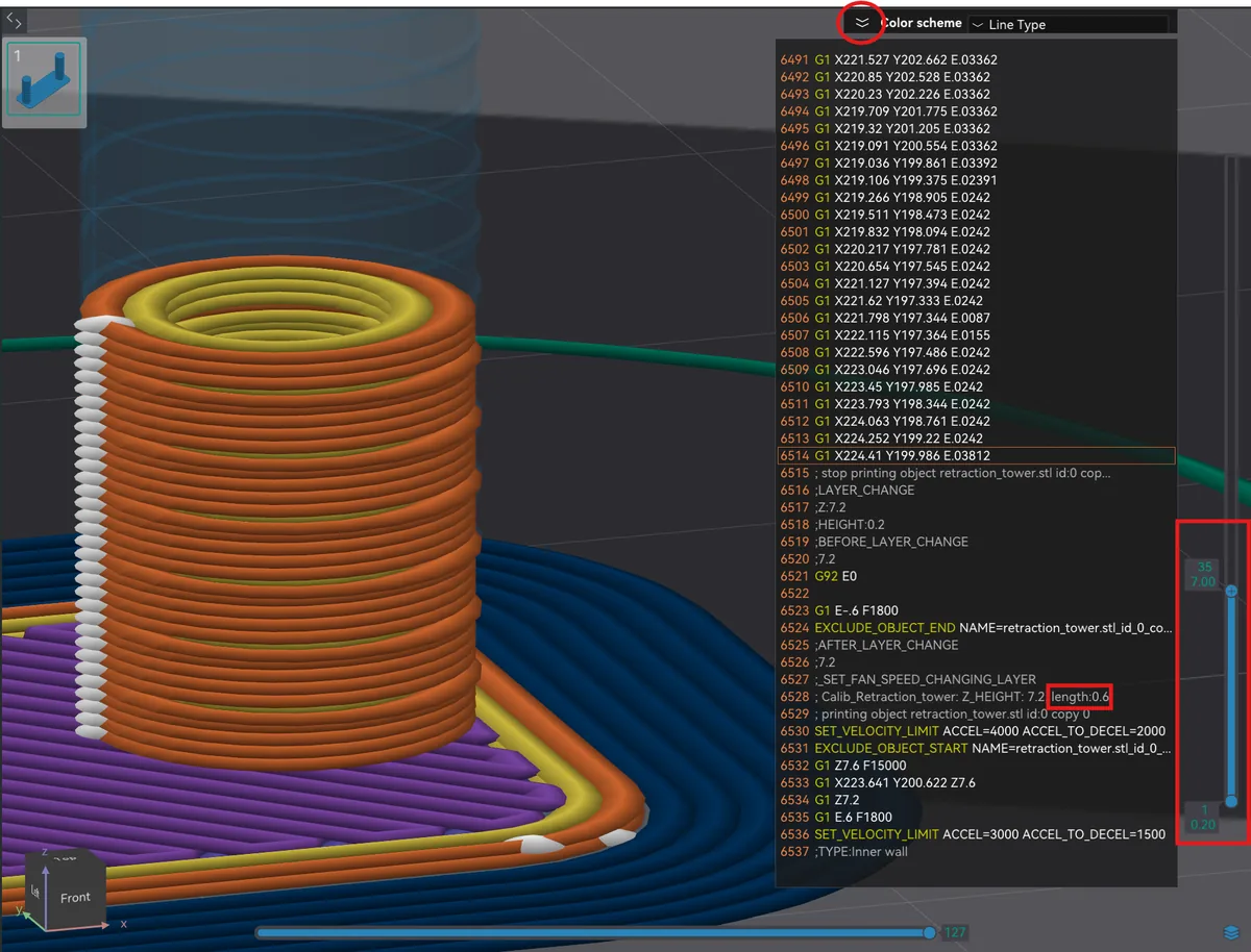
G-code preview slider used to read the retraction length of 0.6 mm for the chosen ring - Add that retraction value to the filament preset.
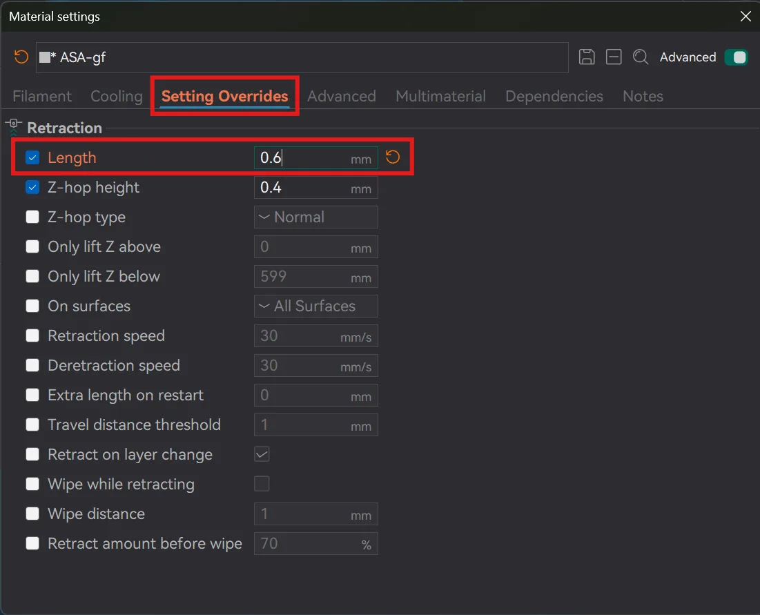
Retraction length 0.6 mm entered under Setting Overrides in the filament preset
Never set retraction to 0. With high retraction values the printer can leave small holes that mimic wet filament.
5. Max Flow Rate
Flow rate vs max flow rate: flow rate is the flow across your whole print at different speeds and accelerations, but it is capped by the max flow rate found here.
- Create a new project within your slicer.
- In the upper right-hand corner, use the calibration drop-down, select More, then Max flowrate.
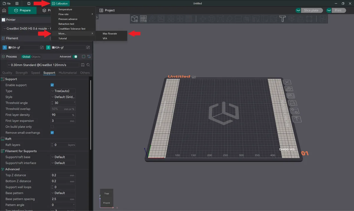
CreatWare calibration menu with More expanded and Max flowrate selected - Adjust the start, end and step values for the filament used, and press OK.
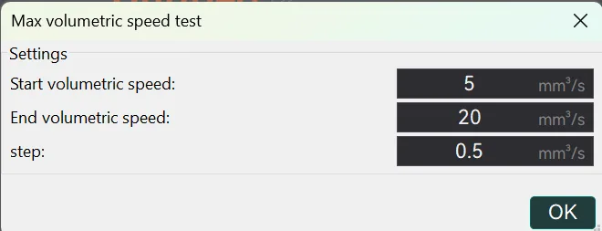
Max volumetric speed test dialog set from 5 to 20 cubic mm per second in 0.5 steps - Slice the part and print.
- Analyse the print. Working top to bottom, find the first good layer without defect.
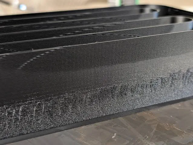
Close-up of the printed max flow rate part showing where the surface degrades - Measure from the base of the print to that layer, set the preview colour scheme to Flow, match the measurement with the slider, then subtract 10–15% from the flow shown and enter it in the filament preset.
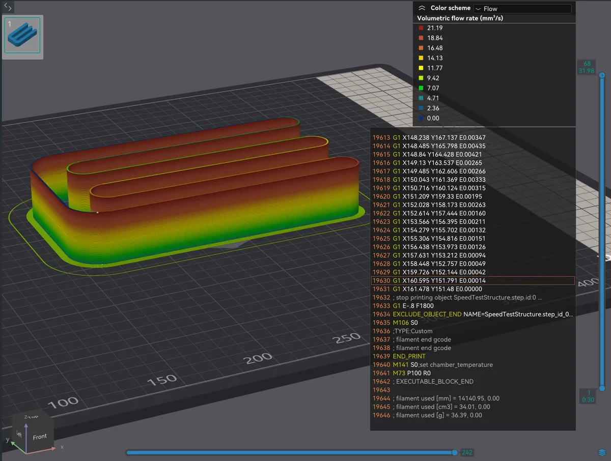
Slicer preview with colour scheme set to Flow showing the volumetric flow rate scale 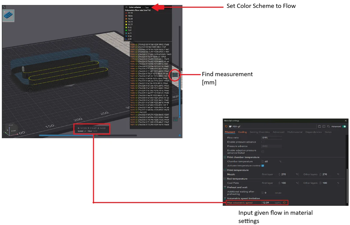
Measuring the defect height, reading the flow value and entering max volumetric speed in material settings
The standard settings suit most filaments. Some high-speed filaments exceed 20 mm³/s — Rev1 PLA Ultra is built for that envelope — while flexibles such as Rev1 TPU 95A need a much lower start, around 2 mm³/s.
Related from Rev1
- Shop 3D printing filament — every spool lists its temperature range
- FDM / FFF 3D printers — machines whose slicers include these routines
- 3D printing services — send us the part if you would rather not dial it in