From version 15 onward, Artec Studio includes the ability to work with CAD objects, enabling you to either create CAD primitives and export them as CAD files or import CAD designs from external software. This functionality supports various tasks, such as:
- Designing and modifying new parts for existing objects.
- Reverse engineering scanned objects.
- Performing quality control by comparing scanned models with their CAD designs.
Types of CAD Primitives
As of version 17, Artec Studio offers two types of CAD primitives:
- Fitted CAD Primitives: These are constructed by fitting the primitives into specific parts of a mesh.
- Independent CAD Primitives: These are created separately from any mesh and can be positioned freely.
Available primitives include:
- Cylinder
- Cone/Truncated cone
- Sphere
- Plane
- Torus
- Box
Additionally, Artec Studio supports specialized surface primitives:
- Freeform Patch: This is useful for wrapping a surface around complex, non-standard shapes, such as organic forms.
- Autosurface: This helps quickly approximate organic shapes into CAD models and is particularly useful for large meshes.
Constructing CAD Primitives
You can create two types of CAD primitives: fitted and independent.
Constructing Fitted CAD Primitives
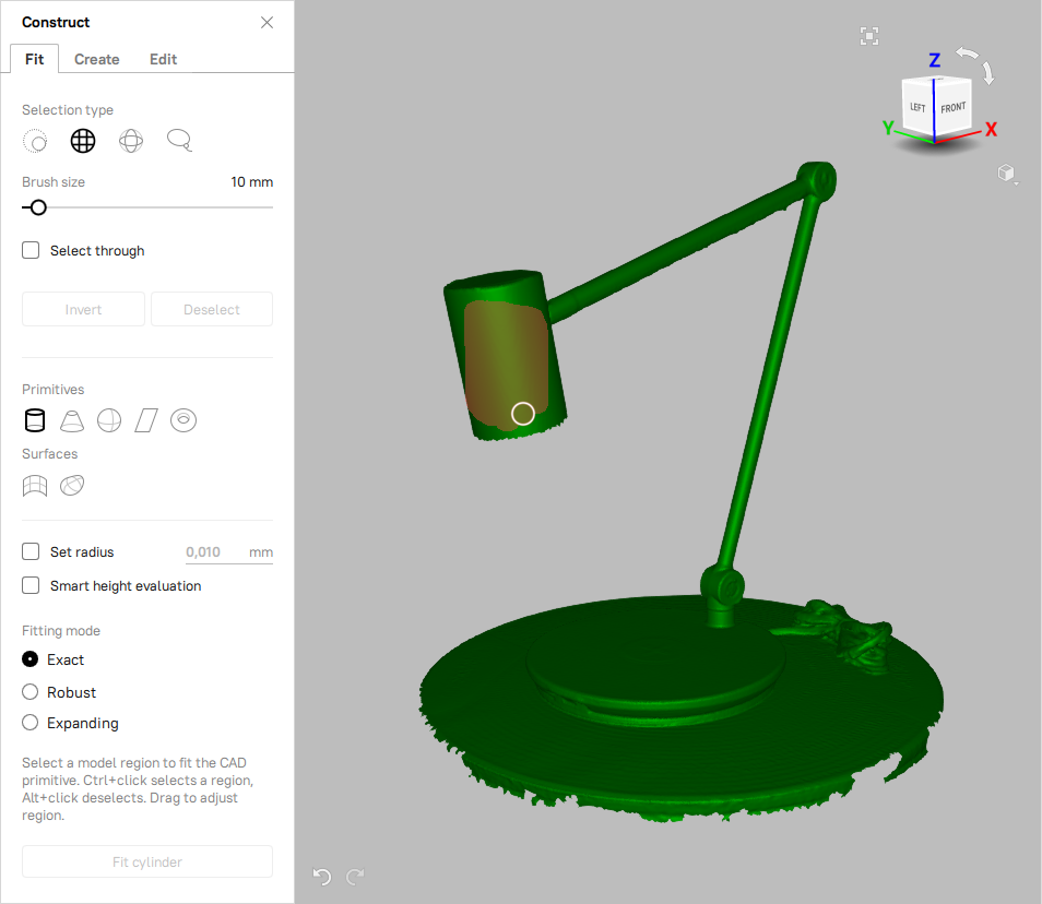
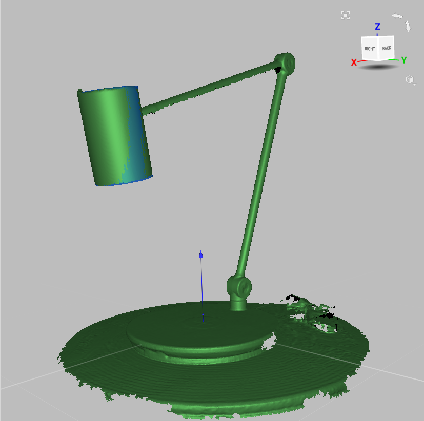
Fitted CAD primitives are based on polygonal meshes and tailored to fit selected areas of the model. For instance, to construct a fitted cylinder:
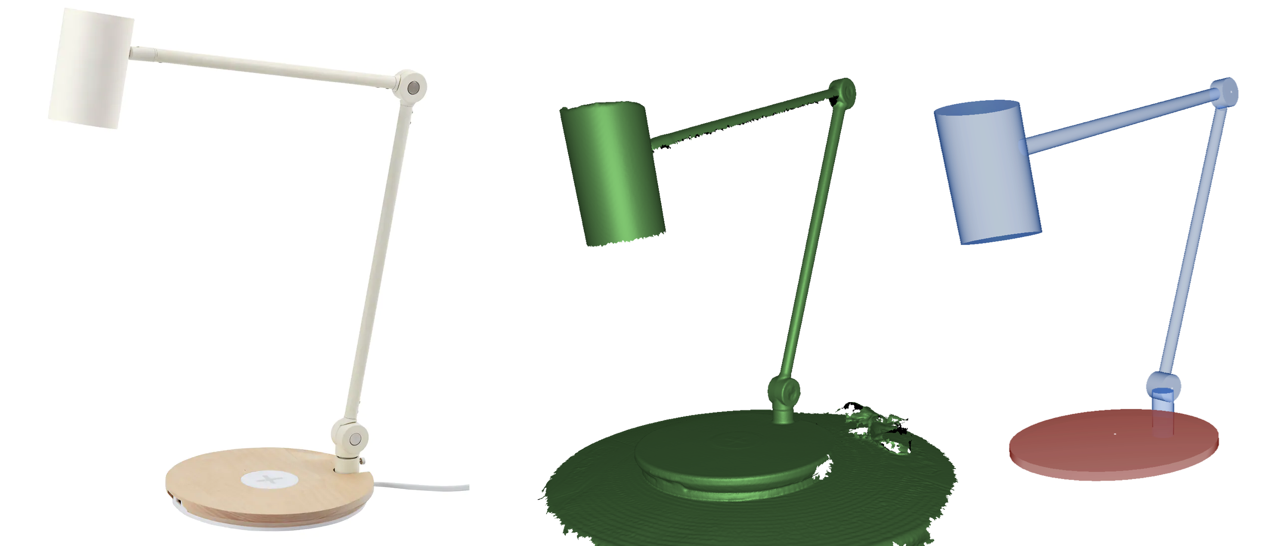
- Load the polygonal model.
- Open the "Construct" panel and access the "Fit" tab.
- Select the desired primitive type (e.g., Cylinder).
- Choose the selection tool (e.g., 2D brush, 3D brush, or Lasso) to define the area on the model.
- Pick a fitting mode—Expanding, Robust, or Exact.
- Click on the primitive icon (e.g., Cylinder) to generate the fitted primitive.
- If needed, adjust parameters such as the radius for a cylinder.
- Confirm the creation by clicking "Fit."
Constructing Independent CAD Primitives
To create independent CAD primitives, follow these steps:
- Open a new project or load a model you wish to modify.
- Navigate to the "Create" tab within the "Construct" panel.
- Select the type of primitive you want to create (e.g., Cylinder).
- Define the parameters, such as radius and height for a cylinder.
- Position the primitive using translation and rotation tools as needed.
- Finalize by clicking the "Create" button.
CAD Primitive Properties
To view the properties of a CAD primitive:
- Select the primitive in the Workspace panel.
- Expand the "Properties" section at the bottom of the panel.
- Depending on the type of primitive, various geometric parameters such as radius, height, and faces will be displayed.
Converting CAD to Mesh
Artec Studio allows converting CAD models and primitives into meshes:
- Select the CAD object within the Workspace.
- Right-click and choose "Convert CAD to Mesh."
- Adjust the detail level by modifying the "Accuracy" setting as needed.
- Click "Run" to complete the conversion.
Applying Constraints to CAD Primitives
After creating CAD primitives, you can adjust their size and positioning by applying constraints. Artec Studio supports two types of constraints:
- Conditions: Apply to a single primitive.
- Relations: Apply between two or more primitives.
To apply constraints:
- Select the primitive and choose the appropriate constraint from the "Constrain" toolbar (e.g., parallel, perpendicular, or coaxial).
- Click "Refit" to apply the constraints and adjust the primitives accordingly.
Boolean Operations
Artec Studio includes basic Boolean operations, which enable you to:
- Unify: Merge multiple objects into a single mesh.
- Subtract: Remove one object from another.
- Intersect: Create a new object from the overlapping regions of two or more objects.
To perform a Boolean operation:
- Go to the "Edit" tab in the "Construct" panel.
- Select the desired Boolean operation.
- Choose the objects involved in the operation.
- Click "Create Mesh" to generate the resulting mesh.
Splitting Objects by Surface
You can divide a mesh or CAD object into segments using pre-defined surfaces or planes. This feature is particularly useful for preparing models for 3D printing.
To split an object:
- Select the object and surfaces within the "Edit" tab of the "Construct" panel.
- Click "Apply" to perform the split.
Working with Imported CAD Models
Imported CAD models can be aligned or compared with polygonal meshes. For precise alignment, avoid nonrigid alignment methods and use multiple point pairs.