CAD Modeling Services
Parametric solid models, class-A surfaces, large assemblies, and drawing packages — built by engineers who model for a living. Rev1 Technologies turns sketches, specs, scan data, and dead legacy files into clean, editable CAD.
Based in Auburn Hills, Michigan, serving Michigan, Ohio, and Indiana and working with teams nationwide. Every model ships with a feature tree you can actually open, edit, and hand to the next engineer.
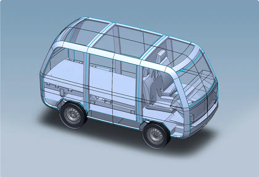
Need a model built, rebuilt, or rescued?
Send us a part, a scan, a sketch, or a file that won't open cleanly — tell us what you need to do with the finished model — and we'll come back with an approach, scope, and timeline, usually within one business day.
Models built to be edited — not rebuilt from scratch.
The difference between a CAD model and a good CAD model shows up six months later, when someone has to change it. We build history-based solid models with deliberate feature ordering, sketch-level constraints that fully define geometry, and named datums so a dimension change ripples cleanly through the part instead of collapsing the tree.
- Fully constrained sketches — no floating geometry, no ambiguous references, no surprise rebuild failures.
- Intentional feature order — base features first, cosmetic features last, so edits stay local and predictable.
- Design tables & configurations — one parent model driving a family of sizes, lengths, or bolt patterns.
- Robust external references — skeleton sketches and layout geometry instead of brittle face-to-face links.
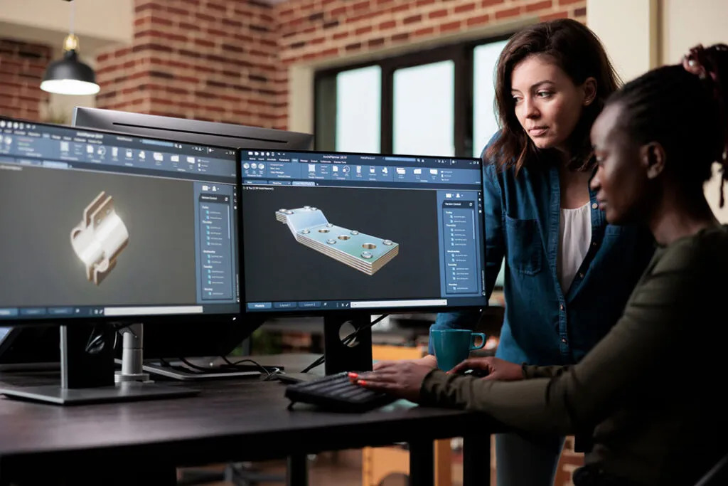
Every kind of CAD work, from a single bracket to a migrated part library.
Engage us for one model, an overflow burst when your own CAD team is buried, or a long-running program. Each capability stands alone and feeds the next.
Parametric solid modeling
History-based part and assembly models with clean, editable trees.
- Fully constrained sketches
- Configurations & design tables
- Native and neutral output
Scan-to-CAD reverse engineering
Physical part in, editable parametric feature tree out.
- Geomagic Design X workflow
- Feature-based, not mesh-wrapped
- Deviation-checked against scan
Class-A & freeform surfacing
Continuity-controlled surfaces for visible, styled, or flowing geometry.
- G2 / G3 curvature continuity
- Zebra & curvature-comb checks
- Surface-to-solid conversion
Large assembly modeling
Hundreds or thousands of components that still open and rebuild.
- Skeleton / layout-driven structure
- Simplified & lightweight configs
- Interference & clearance checks
2D drawings & GD&T
Manufacturing prints that leave nothing open to interpretation.
- ASME Y14.5 GD&T annotation
- Datum schemes & tolerance stacks
- BOMs, balloons & revision blocks
File translation & repair
Get geometry moving between systems without losing it.
- STEP / IGES / Parasolid / native
- Heal gaps, slivers & bad topology
- Feature recognition on dumb solids
Legacy part digitisation
Paper prints, obsolete parts, and shelf spares turned into CAD.
- Drawing-to-model recreation
- Scan-based capture of spares
- Dimensional record for reorder
CAD data migration
Move a part library to a new system without starting over.
- Batch translation & validation
- Re-parameterise critical parts
- Naming, metadata & revision mapping
Model cleanup & remastering
Fix the inherited model everyone is scared to open.
- Rebuild-error triage
- Tree reordering & re-constraining
- Defeature for sharing or analysis
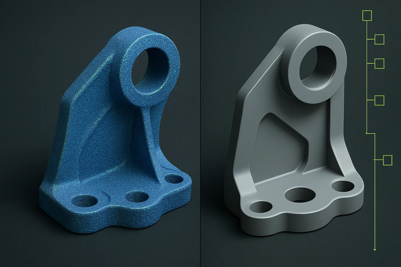
A physical part in — a real feature tree out.
Most "reverse engineering" stops at a wrapped mesh: watertight, pretty, and completely uneditable. We go further. Working in Geomagic Design X, we segment the scan into recognised regions, extract the underlying design intent — the planes, axes, revolves, extrudes, fillet radii and bolt-circle patterns — and rebuild the part as a native, history-based solid you can dimension and change. Capture is handled by our 3D scanning service.
- Feature-based rebuild — sketch-driven solids with editable dimensions, not a frozen surface skin.
- Deviation verification — colour-map the finished model back against the original scan so you see exactly where it lands.
- Nominal vs. as-built judgement — we model the part as it was designed, not with the wear, draft error, and warp baked in, unless you want the as-built condition captured.
- Mesh handling — Geomagic Wrap for point-cloud cleanup, hole filling, and decimation before modeling starts.
- In-CAD workflows — Geomagic for SolidWorks and DezignWorks for scan-to-CAD carried out directly inside your modeling environment.
The software we model in — and the software we sell.
Rev1 supplies and supports these packages to engineering teams across the Midwest, which means the people modeling your part are the same people who train others on the tool.
The core of our reverse engineering work. Region segmentation, automatic feature extraction, and a live history tree that exports as native CAD — the difference between an editable model and a dead mesh.
Registration, noise removal, hole filling, decimation, and mesh repair. Clean input data is the single biggest factor in how good the resulting model is, so this step is never skipped.
Reverse engineering carried out directly in the SolidWorks environment, so the finished part lands natively in your existing tree, assemblies, and drawing templates.
Drives portable arms and scanners straight into the CAD session, letting us build features from measured geometry in real time — useful for fixtures, mating faces, and in-situ capture.
Direct, history-free editing for geometry that has no tree to begin with: imported dumb solids, translated files, defeaturing for analysis, and fast healing of gaps and sliver faces.
STEP (AP203 / AP214 / AP242), IGES, Parasolid, STL, and the native format your team actually works in. Tell us the downstream system and we match it.
Where solids stop, surfacing starts.
Some geometry simply cannot be extruded and filleted into existence — body panels, ergonomic grips, aerodynamic fairings, blended transitions between features that meet at awkward angles. That work is built surface by surface, with continuity controlled deliberately at every boundary and inspected before anything is knitted into a solid.
- Curvature continuity — G0, G1, G2 and G3 boundaries chosen per edge, so highlights flow instead of breaking at a seam.
- Visual inspection — zebra stripes, curvature combs, and reflection maps used as an actual gate, not a screenshot for the report.
- Scan-driven surfacing — fit clean, controlled surfaces to scanned freeform shapes rather than draping a mesh.
- Surface-to-solid — knit, thicken, and close into a watertight solid ready for machining, tooling, or printing.
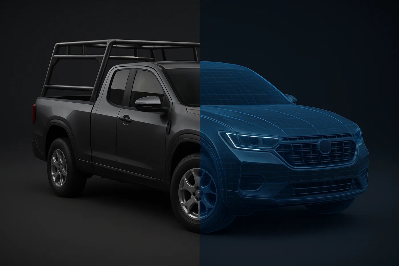
Assemblies that still open on Monday morning.
Assembly problems are rarely geometry problems — they are structure problems. Mate everything to everything and a thousand-component machine becomes unopenable. We build assemblies on a skeleton: layout sketches and reference geometry carry the critical dimensions, sub-assemblies are grouped the way the machine is actually built and serviced, and mates reference stable datums rather than arbitrary faces.
- Skeleton-driven structure — top-level layout geometry drives the parts, so one dimension change updates the whole machine.
- Build-order sub-assemblies — grouped to match how the thing is assembled on the floor, not how the files landed in a folder.
- Performance configurations — simplified and lightweight representations so the model stays usable on normal hardware.
- Interference & clearance — static interference checks plus motion clearance through the range of travel.
- Structured BOMs — multi-level bills of material that reconcile with the drawing set and your part numbering.
Scope → Model → Verify → Release.
The same four steps whether we're building a bracket from a sketch or rebuilding a two-thousand-part library.
Scope
We establish what the model is for — machining, moulding, analysis, marketing, archive — because that determines how it should be built. We agree the target CAD system, format, tolerance intent, and level of detail up front.
Model
We build the geometry: sketch-driven solids, surfaced freeform regions, or a scan-derived feature tree. Naming conventions and datum schemes follow your standards if you have them, ours if you don't.
Verify
Rebuild-error check, geometry validation, interference check on assemblies, and — on reverse-engineered parts — a deviation colour map back against the source scan so accuracy is demonstrated, not asserted.
Release
Native files, neutral exports, drawings with GD&T, and a short model note covering how the tree is structured and which parameters drive what — so your team can pick it up cold.
Prints that a shop can quote without calling you.
A model tells a machinist the shape. A drawing tells them what actually matters. We produce fully annotated manufacturing drawings with a coherent datum scheme and geometric tolerances applied where function demands them — and left open where it doesn't, because over-tolerancing is one of the most expensive habits in engineering.
- ASME Y14.5 GD&T — position, profile, flatness, perpendicularity, runout, applied with a defensible datum reference frame.
- Tolerance stack-ups — worst-case and statistical stacks that show whether the assembly actually closes.
- Complete drawing sets — section and detail views, ballooned BOMs, weldment and assembly sheets, revision blocks and title-block data.
- Inspection-ready — drawings dimensioned so they can be balloted straight into a first-article inspection report.
- MBD annotation — model-based definition with PMI carried in the 3D file where your process has moved past paper.
When the file opens as an error message.
Geometry moving between CAD systems loses its history and often its integrity — gaps, sliver faces, inverted normals, tolerance mismatches. Here's what each format carries and how we handle what arrives broken.
| Format | What it carries | What we do with it |
|---|---|---|
| STEP (AP203 / AP214 / AP242) | Solid and surface B-rep geometry; AP242 adds PMI and product structure. | Primary neutral exchange format. We validate solid integrity on import and can recognise features to restore an editable tree. |
| IGES | Surfaces and curves; frequently arrives as an unstitched surface soup. | Stitch, heal gaps, close the body, and knit to a watertight solid before any downstream work. |
| Parasolid (x_t / x_b) | High-fidelity kernel geometry between Parasolid-based systems. | Cleanest transfer when both ends share the kernel — usually the least lossy route we can offer. |
| Native CAD files | Full history tree, parameters, configurations, and drawing links. | Delivered natively where you need parametric editing, so nothing is flattened on handover. |
| STL / OBJ / mesh | Faceted triangles only — no curvature, no features, no editability. | Cleaned in Geomagic Wrap, then rebuilt as real CAD when you need more than a print file. |
| Point clouds & scan data | Raw measured geometry from structured-light or laser scanning. | Registered, decimated, and reverse-engineered into a parametric model with deviation verification. |
| 2D drawings (DWG / DXF / paper) | Dimensioned views with no associated 3D model. | Interpreted and rebuilt as a 3D parametric model, with ambiguities flagged for your review rather than guessed. |
Getting decades of geometry into a system you can still use.
Two problems that look different and are really the same one: valuable geometry trapped in a form nobody can edit.
Legacy part digitisation
Parts that predate your CAD system — or predate CAD.
- Paper and film drawings rebuilt as 3D parametric models, with dimensional conflicts flagged instead of silently resolved.
- Obsolete components with no drawings and no supplier, captured by 3D scan and rebuilt as an editable model you own outright.
- Shelf spares digitised while stock still exists, so the last physical unit stops being a single point of failure.
- Hand-modified prototypes where the shop-floor changes never made it back into the record.
- Tooling and fixtures captured before they wear out or get scrapped.
CAD data migration
Changing CAD systems without losing ten years of work.
- Triage first — not every part deserves a parametric rebuild. We sort the library into translate-as-is, re-parameterise, and retire.
- Batch translation with automated geometry validation, so failures surface as a report rather than as a surprise months later.
- Selective re-parameterisation of the parts that actually get edited, rebuilt as proper feature trees in the new system.
- Metadata mapping — part numbers, revisions, materials, and custom properties carried across rather than retyped.
- Drawing regeneration so the 2D set stays associated with the migrated 3D geometry.
Model it once. Model it properly.
A well-built tree costs a little more today and saves every engineer who touches it afterwards. Send us the part, the scan, or the broken file and we'll tell you honestly what it needs.
We scan it, we model it, and we can measure whether we got it right.
Reverse-engineered models are verified against the source scan with a deviation colour map. Accuracy is demonstrated on a report, not claimed in an email.
Rev1 supplies and supports Geomagic Design X, Geomagic Wrap, Geomagic for SolidWorks, DezignWorks, and Ansys SpaceClaim — so your model is built by people who train others on the exact software.
Named features, logical ordering, fully constrained sketches, and a short model note explaining what drives what. Handover is part of the deliverable.
Scanning, modeling, and dimensional inspection sit under one roof in Auburn Hills, so there's no handoff gap between measuring a part and modeling it.
NDAs are standard. Your geometry, drawings, and part libraries stay yours, and we don't reference client names in our own marketing.
Auburn Hills, Michigan — close enough to Michigan, Ohio, and Indiana teams to have a part on the scanner the same week, and working with clients nationwide.
CAD work for industries where the model has to be right.
Automotive & mobility
Component and fixture models, class-A surfacing on visible geometry, and scan-based rebuilds of legacy tooling and service parts.
Aerospace & defense
Tight-tolerance parametric models, rigorous GD&T schemes, and digitisation of obsolete hardware with no surviving drawing package.
Medical & dental
Freeform and ergonomic geometry, housings and instruments, and accurate models where surface quality is part of the specification.
Industrial & automation
Large machine assemblies, custom tooling and fixture models, and structured BOMs that reconcile with the drawing set.
Consumer products
Class-A surfaced enclosures, parametric families across a product range, and production-ready models with full drawing sets.
Energy & heavy equipment
Large weldments and castings, reverse-engineered wear parts, and legacy component libraries brought into a current CAD system.
A sample of the modeling problems we solve.
Representative examples across the industries we serve. Details are genericized to protect client confidentiality.
Obsolete gearbox housing rebuilt as parametric CAD
Heavy equipment · Scan-to-CAD
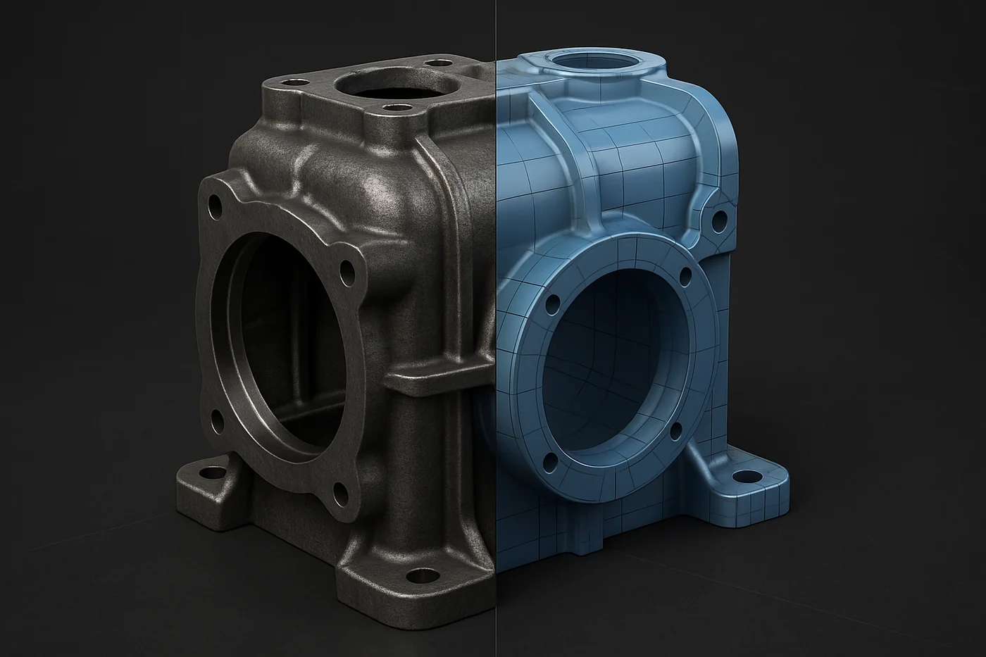
An equipment operator had a cast housing still in service with no drawings and no supplier. We scanned the part, rebuilt it in Geomagic Design X as a feature-based solid — recovering the design-intent bore axes, bolt patterns, and fillet radii rather than freezing in the casting's wear and draft variation — then delivered a deviation report showing the model against the scan, plus a fully toleranced drawing package for requote.
Class-A enclosure surfaced from a physical styling model
Consumer products · Surfacing
A product team had a hand-finished appearance model and no usable CAD. We scanned it and built controlled class-A surfaces to G2 continuity across the visible faces, verified with zebra and curvature analysis, then knitted the result into a solid with a proper parametric tree for the internal features — so styling and engineering worked from one model.
Two-thousand-part library migrated to a new CAD system
Industrial automation · Data migration
A machine builder changed CAD platforms and faced a decade of geometry stranded in the old system. We triaged the library into translate, rebuild, and retire; batch-translated with automated validation reporting; re-parameterised the several hundred parts that actually get edited; and mapped part numbers, revisions, and material properties across so nothing was retyped.
Tier-1 supplier's inherited assembly rescued
Automotive · Model cleanup
A tier-1 automotive supplier inherited an assembly that took twenty minutes to open and threw rebuild errors on every edit. We restructured it onto a skeleton layout, replaced brittle face-to-face mates with datum references, re-constrained the underdefined sketches, and added simplified configurations — leaving a model their team could edit in minutes instead of avoiding.
What lands in your hands at the end.
Native CAD
The parametric model in your system, with a live, editable history tree — not a flattened import.
Neutral exports
STEP, IGES, Parasolid, and STL as required, so suppliers and downstream systems are covered.
Drawing package
Dimensioned manufacturing drawings with GD&T, BOMs, revision blocks, and your title-block standard.
Deviation report
On reverse-engineered parts, a colour-map comparison of the finished model against the source scan data.
Model notes
A short written handover: tree structure, driving parameters, datum scheme, and any assumptions we made.
Source data
The cleaned mesh or point cloud where scanning was involved, so you keep the measured record too.
CAD modeling is one piece of it.
Need the part captured, the design developed, or the finished geometry made? Those live next door.
3D Scanning
Metrology-grade capture of physical parts — the input side of every scan-to-CAD and legacy digitisation job on this page.
Explore 3D scanning →Engineering & Product Design
The full design service: design-for-manufacture, simulation-driven design, and product and industrial design from concept onward.
Explore design services →Manufacturing & Prototyping
Turn the finished model into real parts — additive, CNC, casting, and low-volume production.
Explore manufacturing →CAD modeling — common questions.
What does your CAD modeling service cover?
Parametric solid modeling, scan-to-CAD reverse engineering into editable feature trees, class-A and freeform surfacing, large assembly modeling, 2D drawings with GD&T annotation, CAD file translation and repair, legacy part digitisation, and CAD data migration between systems.
Will I get an editable model or just a mesh?
An editable model. Even on reverse-engineered parts we rebuild the geometry as a history-based parametric solid in Geomagic Design X, with sketches and features you can dimension and change. A wrapped mesh is only delivered if that is specifically what you asked for.
How accurate is a reverse-engineered CAD model?
Accuracy depends on the scanning hardware, part size, and surface condition, so we quote it per job rather than publishing a blanket figure. Every reverse-engineered model ships with a deviation colour map comparing the finished CAD against the source scan, so you can see the actual result rather than take our word for it.
Do you model the part as designed or as it is now?
Your call, and it matters. Most customers want design intent recovered — nominal bores, true axes, clean bolt circles — with the wear, warp, and casting variation left out. If you need the as-built condition captured instead, for example to investigate a failure, we model that. We confirm which before starting.
What CAD formats do you deliver?
Native files in your modeling system plus neutral exports: STEP (AP203, AP214, or AP242), IGES, Parasolid, and STL. Tell us what your suppliers and internal systems need and we match it.
Can you fix a file that won't import properly?
Usually. Translated geometry commonly arrives with gaps, sliver faces, or unstitched surfaces. We heal the topology, stitch it into a watertight solid, and where useful run feature recognition to restore an editable tree on what arrived as a dumb solid.
Can you work in our CAD system and to our standards?
Yes. We match your target system, drawing templates, title blocks, layer and naming conventions, and datum practice. If you don't have documented standards, we apply ours and hand over a note describing them.
Can you handle large assemblies without the file becoming unusable?
Yes — that's a structure problem more than a geometry one. We build on skeleton layouts, group sub-assemblies to match how the machine is actually built, mate to stable datums, and provide simplified and lightweight configurations so the model opens and rebuilds on normal hardware.
Do you apply GD&T or just dimensions?
Full GD&T to ASME Y14.5 where the part warrants it, with a defensible datum reference frame and tolerance stack-ups to confirm the assembly closes. We also deliberately avoid over-tolerancing, because tight callouts where function doesn't need them are one of the most expensive habits in engineering.
How is this different from your design service?
This page is about building the geometry itself — modeling, surfacing, assemblies, drawings, and file work. Our engineering and product design service covers the broader development effort: design-for-manufacture, simulation-driven design, and product and industrial design. Many projects use both.
Do you scan the part too, or do I send data?
Either. We scan in-house with metrology-grade equipment through our 3D scanning service, or we work from mesh and point-cloud data you supply. If you're sending data, tell us how it was captured so we can judge what the model can reasonably be built to.
Where are you located and who do you serve?
Rev1 Technologies is in Auburn Hills, Michigan, serving customers across Michigan, Ohio, and Indiana and working with teams nationwide. NDAs are standard, so your geometry, drawings, and part libraries stay confidential.
For immediate assistance:
(248) 707-2950
For immediate assistance:
…