Metrology & Dimensional Inspection
Proof your part is in tolerance — in a report your customer's quality team will accept.
GD&T verification, first-article inspection, PPAP support, and incoming / in-process quality inspection from Rev1's Auburn Hills, MI metrology lab. Balloon-numbered reports, colour-deviation maps, and full GD&T tables built in PolyWorks Inspector and Geomagic Control X. Serving Michigan, Ohio, Indiana and Illinois, with on-site inspection nationwide.
Need the part digitised first? That's 3D scanning & capture. Want both capture and inspection in one scope? Start at the 3D scanning & metrology overview.
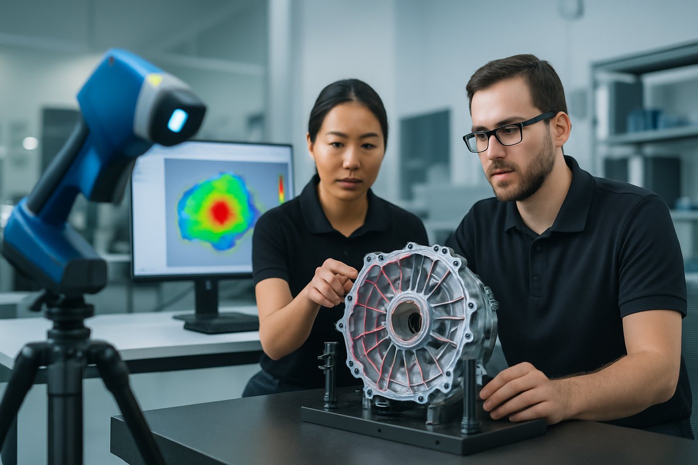
Measurement is the easy part. The report is the deliverable.
Anyone can put numbers on a part. Dimensional inspection is the discipline of proving those numbers against a drawing, a datum scheme, and a tolerance stack — then documenting it so a quality engineer three companies downstream can sign off without a phone call. That documentation is what Rev1 builds.
Dimensional analysis
Every callout on the print measured, recorded, and judged pass / fail against its stated tolerance — not eyeballed off a mesh.
- Balloon-numbered drawing capture
- Feature-by-feature actual vs nominal
- Out-of-tolerance flagged and quantified
GD&T verification
Geometric tolerances evaluated against the drawing's datum reference frame — position, profile, flatness, runout, perpendicularity, concentricity.
- Datum alignment before evaluation
- Material condition modifiers applied
- Bonus tolerance calculated, not ignored
Quality documentation
The paperwork your customer's supplier-quality group actually asks for, formatted the way they expect to receive it.
- AS9102-format first-article packages
- Colour-deviation atlases
- Excel / CSV data for your SPC system
Datums first. Then the tolerance zone. Then the verdict.
Most "inspection reports" that land on a quality desk are a deviation colour map with no datum scheme behind it. That is a shape comparison, not a GD&T evaluation — and it will not survive a supplier audit. Rev1 builds the datum reference frame from the print before a single tolerance is judged, so the numbers on the report mean what the drawing says they mean.
- Datum-driven alignment — primary, secondary and tertiary datums established per the feature control frame, not a best-fit to the whole part.
- Full geometric characteristic set — true position, profile of a surface and line, flatness, straightness, circularity, cylindricity, perpendicularity, angularity, parallelism, runout and total runout, concentricity.
- MMC / LMC handled properly — material condition modifiers applied and bonus tolerance reported explicitly, so borderline features are not failed by accident.
- Composite and multi-datum frames — pattern-locating and feature-relating tolerance zones evaluated separately, the way the standard intends.


First article inspection, balloon to sign-off.
A first article is a promise that the process — not just the part — is capable. Rev1 runs FAI as a documentation exercise from the start: the drawing is ballooned, every characteristic is assigned a number, and every number gets an actual, a tolerance, and a disposition. Nothing is left as "visually acceptable."
- AS9102-format packages — Form 1 part accountability, Form 2 raw material and process certification references, Form 3 characteristic accountability, delivered as the report format for aerospace and defence programs.
- Balloon-numbered prints — a marked-up drawing that maps 1:1 to the results table, so a reviewer can trace any line item back to the callout it came from.
- Delta FAI on change — partial re-inspection scoped to the characteristics a design revision, tooling change, or process move actually touched.
- Non-conformance handling — out-of-tolerance features isolated, quantified, and photographed so your team can build the corrective action rather than re-measure to find it.
Catch the bad lot at receiving, not at assembly.
The cheapest non-conformance is the one caught before it enters your line. Rev1 runs incoming inspection on supplier shipments and in-process inspection between operations — sampled or 100%, one-off or as a standing program — with the same measurement chain and the same report format every time, so trends are comparable month over month.
- Incoming / receiving inspection — verify a supplier lot against the purchase drawing before it is stocked. Sampling plans agreed up front, not improvised.
- In-process inspection — measure between operations to confirm a machining or forming step landed before value is added on top of a scrap part.
- Repeat-lot trending — the same characteristics measured the same way across shipments, exported to Excel / CSV so your SPC system can consume it directly.
- Supplier dispute resolution — an independent third-party measurement when you and your supplier disagree about whose gauge is right.


Validate the tool. Then monitor what it does to itself.
A die that was correct at T1 is not necessarily correct at 200,000 hits. Rev1 inspects tooling at build-off, then re-inspects on a schedule against the original as-built condition — so wear is a trend line you plan around instead of a scrap report you react to.
- Tryout and build-off validation — as-built cavity, core, and forming surface compared to the released CAD before the tool ships or is accepted.
- Wear monitoring over life — scheduled re-inspection compared to the T0 baseline, isolating where material has been lost and by how much.
- Springback and compensation data — formed-part geometry versus tool geometry, quantified so the compensation cut is informed rather than iterative.
- Fixture and gauge certification — check the fixture itself, because an out-of-position locator turns every part it holds into a false reject.
PPAP support: the dimensional evidence, done properly.
Rev1 is not your quality department and does not submit your PPAP for you. What Rev1 supplies is the dimensional-results element and the measurement evidence behind it — the part of the submission that most often gets a package rejected — built to the format your customer specified.
Every characteristic, measured and accounted for.
A complete results table tied to a ballooned print: characteristic number, nominal, tolerance, actual, disposition. The line-by-line evidence a customer quality engineer reads first.
Proof the measurement itself is defensible.
Method, equipment, alignment scheme, and calibration traceability documented alongside the numbers, so the results can be reproduced and audited rather than taken on trust.
Multi-piece data ready for Cp / Cpk.
Measure a run of consecutive parts on the same characteristics with the same setup, and receive the raw dataset in a form your statistics package can consume directly.
Annual layout and re-validation runs.
Scheduled full-characteristic re-inspection to satisfy periodic layout requirements, run against the same datum scheme as the original submission so results are directly comparable.
CMM or optical? The part decides, not the sales pitch.
Tactile CMM probing and optical / structured-light measurement are different instruments with different strengths, and a shop that only owns one will always tell you its instrument is the right one. Rev1 selects the method per characteristic — and on a lot of parts, the honest answer is both.
| Consideration | Tactile CMM / portable arm | Optical & structured light |
|---|---|---|
| Data model | Discrete probed points on selected features. | Dense full-surface point cloud — millions of points per second. |
| Best on | Prismatic features: bores, planes, tapped holes, deep pockets, tight feature-level probing on rigid parts. | Free-form and sculpted surfaces, sheet metal, castings, large fabrications, whole-part profile. |
| Speed on complex geometry | Slow — every point is a discrete touch, and coverage is only as good as the probing plan. | Fast — the whole surface is captured at once, so nothing is missed for lack of a planned point. |
| Profile & deviation mapping | Limited — interpolated between probed points. | Native — a full colour deviation map of the entire surface against nominal. |
| Deep or occluded features | Strong — a stylus reaches where a line of sight cannot. | Weak — anything the sensor cannot see, it cannot measure. |
| Reflective & transparent surfaces | Unaffected by finish. | May need a temporary matting treatment before capture. |
| Flexible / thin-wall parts | Probe force can deflect the part and bias the reading. | Non-contact — no probing force, no deflection. |
| Typical Rev1 call | Feature-level GD&T on rigid, prismatic machined parts. | Surface-driven work, whole-part profile, deviation atlases, large or flexible parts. |
Rev1 prefers optical for surface-driven work; arm CMMs remain best for tight feature-level probing on rigid parts. Hybrid scopes — optical for profile, tactile for the handful of features that demand it — are routine, not an exception. Capture hardware and how the data is acquired is covered on 3D scanning & capture.
Reports built to be read by someone who wasn't in the room.
An inspection deliverable has one job: let a reviewer reach the same conclusion you did, without asking you a single question. Everything below is standard output — pick what your customer's quality group actually requires.
Colour deviation maps
Whole-surface actual-versus-nominal comparison rendered as a colour atlas, with the scale, tolerance band, and alignment scheme stated on every view — not a pretty picture with an unlabelled rainbow.
GD&T tables
Feature control frame, datum reference, tolerance zone, measured value, bonus tolerance where applicable, and pass / fail. One row per callout.
Balloon-numbered prints
The drawing marked up so each characteristic carries a number that maps directly to its row in the results table.
AS9102 FAI forms
Forms 1, 2 and 3 completed as the first-article report format, ready to drop into an aerospace or defence submission package.
Cross-section & callout views
Targeted 2D sections and annotated detail views through the features that matter, so a reviewer sees the evidence rather than a global colour wash.
Raw data exports
Excel and CSV results tables for your SPC or quality system, plus the underlying mesh and point-cloud data (STL / OBJ / PLY, E57 / PTS / PCD) on request.
PolyWorks and Geomagic Control X — on production licences.
The software is not a detail. Alignment strategy, GD&T engine behaviour, and report templating all live in the inspection package, and results can differ between packages if the datum scheme is set up carelessly. Rev1 runs the industry-standard tools, on production licences, with factory-trained operators — and sells and supports these platforms, so the depth is not surface-level.
PolyWorks Inspector
Rev1's primary inspection environment for dimensional analysis, GD&T evaluation, and repeat-lot comparison.
- Datum-driven and best-fit alignment strategies
- Full geometric characteristic evaluation against the drawing
- Heat-map PDF reporting plus tabular exports
- Repeat measurement sequences for recurring lot inspection
Geomagic Control X
Used where a customer standardises on Control X, and for fast comparative studies and tooling-wear deltas.
- CAD-to-part and part-to-part comparison
- Colour deviation atlases and cross-section analysis
- Trend comparison across a tool or process over time
- Report output in the format your customer already reviews
Six steps from drawing to signed report.
Every inspection scope runs the same path. The variable is how many characteristics are on the print and how many parts are in the lot — not whether the process gets followed.
Drawing & scope review
Send the print, the model, and what the customer is asking for. We identify the datum scheme, the characteristic count, and anything on the drawing that is ambiguous before quoting.
Inspection plan
Method per characteristic (optical, tactile, or both), fixturing approach, sampling plan, and report format — agreed in writing so there is no scope surprise at delivery.
Fixturing & setup
Part constrained the way the datum scheme requires. Flexible parts supported so gravity is not measured as a defect.
Measurement
Data acquired against a traceably calibrated chain. Coverage confirmed against the plan before the part leaves the fixture.
Analysis & evaluation
Alignment to the datum reference frame, then characteristic-by-characteristic evaluation in PolyWorks Inspector or Geomagic Control X.
Report & review
Deliverable issued in the agreed format, with an engineer available to walk your quality team through any non-conformance and what drove it.
One part, one program, or an engineer on your floor.
Inspection demand is rarely one-shaped. Scope it the way your program actually consumes it.
Single-part inspection.
One part, one report. Ship it in or schedule an on-site visit, receive the dimensional and GD&T report to the agreed format.
Lot & batch inspection.
A sampling plan or 100% inspection across a shipment, reported as a single package with per-part results and a lot-level summary.
Quarterly inspection retainer.
Allocated metrologist and equipment hours per quarter with priority scheduling — for ongoing QC programs that shouldn't be re-quoted every time.
Embedded metrology engineer.
A Rev1 metrologist on-site at your facility, 1–5 days per week, running inspection inside your quality system and training your team on it.
Have a print and a part that need to agree?
Send the drawing and the characteristic count. A Rev1 metrologist scopes the inspection plan and quotes it — no guesswork on either side.
As-built versus as-designed, on a structure that could not move.
An aerospace interiors integrator needed to confirm that an as-built fuselage interior matched the released design envelope closely enough to commit a retrofit package to tooling. The structure could not be shipped, so the measurement went to the structure.

The problem
A retrofit package had to interface with a structure that had been built, modified, and repaired over its service life. Nobody could say with confidence how far the as-built condition had drifted from the drawing.
The approach
Full-envelope capture, registered into one coordinate frame, then evaluated against the released design rather than eyeballed. Interfaces that drove the retrofit were sectioned and dimensioned individually.
The outcome
The integrator committed the retrofit design against measured geometry instead of assumed geometry — and knew, before cutting tooling, exactly which interfaces needed accommodation.
Lab-grade accuracy. Engineering-grade follow-through.
Most inspection vendors hand back a number. Rev1 hands back a number, the datum scheme it was measured against, and an engineer who can explain what to do about it.
Metrology-grade systems with ISO 17025 traceable calibration, for the characteristics where vendor-published accuracy isn't sufficient evidence.
Measurement traceable through an accredited calibration chain. Reports stand up to AS9102 first-article requirements and aerospace audits.
PolyWorks Inspector for GD&T and QC, Geomagic Control X for comparative studies. Production licences, factory-trained operators — we don't fight the wrong tool.
Optical, tactile, or hybrid, chosen against the characteristic rather than against whatever hardware happens to be free that afternoon.
Out-of-tolerance is where our job starts. The same team takes a non-conformance through root cause, redesign, and back into engineering & design.
Most inspection reports deliver in 1–3 business days. Full first-article and multi-part capability packages take 3–7. Rush available on request.
Eight verticals, one measurement chain.
The datum scheme changes. The report format changes. The traceability behind the numbers does not.
Aerospace
First-article packages in AS9102 format, as-built structure validation, retrofit interface verification.
Automotive
Production part approval support, launch containment sorts, and repeat-lot trending for tier suppliers.
Medical Devices
Documented dimensional verification with a traceable measurement chain and an auditable method statement.
Defense
First-article and layout inspection on controlled programs, with NDA and restricted-facility workflows.
Energy & Power
Large fabrication and rotating-component profile verification, plus wear assessment on service-run parts.
Tooling & Dies
Build-off validation, scheduled wear monitoring against the T0 baseline, springback and compensation data.
Contract Mfg
Independent third-party inspection for customer submissions and supplier disputes alike.
Heavy Equipment
Weldment and large-assembly dimensional verification where the part is too big to bring to a bench.
Consumer Products
Free-form surface profile verification and multi-cavity tool comparison across production runs.
The documents that travel with the report.
If your buyer or auditor asks for proof behind the numbers, these are what Rev1 supplies alongside the inspection package.
ISO 17025 Calibration
Dimensional measurement traceable through an accredited calibration chain. Required for aerospace and regulated medical inspection. Cert on file — available with every report.
PolyWorks Inspector Authorized
InnovMetric authorized partner for the Inspector / Modeler / DataLoop stack. Lab uses production licences, not trial or educational.
Geomagic Suite Authorized
Control X inspection, Design X reverse engineering, Wrap mesh processing. Authorized reseller and factory-trained operators.
Where inspection sits in the Rev1 stack.
This page covers what happens after the data exists — evaluation, judgement, and documentation. Capture, the combined overview, and what happens to a failed part all live next door.
3D Scanning & Capture
How the geometry gets digitised: handheld and fixed-station structured light, on-site capture, registration, and mesh processing. The upstream half of any inspection scope.
Explore 3D scanning →3D Scanning & Metrology
The combined hub covering capture and inspection together, including engagement models, service tiers, and the instant scan quoter for scoped scan-to-deliverable work.
See the full overview →Engineering & Product Design
When inspection finds a problem the design has to solve: parametric CAD, reverse engineering, design-for-manufacture, and tolerance work.
Explore engineering & design →Eight things quality teams ask before sending a part.
If your question isn't here, the scoping review is the right place — we don't quote an inspection without seeing the drawing.
What's the difference between this page and 3D scanning?
3D scanning is capture — turning a physical part into measurement data. This page is inspection — evaluating that data against a drawing, a datum scheme, and a tolerance, then documenting the verdict. Many projects need both, which is what the combined 3D scanning & metrology overview scopes.
How accurate is the measurement?
Up to 0.005 mm on metrology-grade systems, backed by ISO 17025 traceable calibration. Not every characteristic needs that floor — the inspection plan states the method and expected uncertainty per characteristic so the accuracy is matched to the tolerance rather than oversold.
Do you do first article inspection to AS9102?
Yes. Rev1 delivers first-article packages in the AS9102 form set — Form 1 part accountability, Form 2 material and process references, Form 3 characteristic accountability — against a balloon-numbered print, with every characteristic carrying a nominal, tolerance, actual, and disposition.
Can you support our PPAP submission?
Rev1 supplies the dimensional-results element and the measurement evidence behind it, plus multi-piece datasets for capability studies. The submission itself stays with your quality department — we build the dimensional evidence it rests on, in the format your customer specified.
Do you use a CMM or optical scanning?
Both, selected per characteristic. Tactile probing is stronger on deep, occluded, and prismatic features; optical is faster and denser on free-form surfaces, sheet metal, castings, and anything where whole-surface profile matters. Hybrid inspection plans are routine — see the comparison above.
What does an inspection report actually contain?
At minimum: a balloon-numbered print, a results table with nominal / tolerance / actual / disposition per characteristic, the alignment and datum scheme used, and a colour deviation map where surface profile is in scope. AS9102 forms, cross-section views, and Excel / CSV exports are added per the agreed format.
Can you inspect at our facility?
Yes. Parts that can't ship — large weldments, installed equipment, in-situ tooling, aerospace structures — are inspected on-site, with the same reporting chain as lab work. NDA and restricted-facility workflows available.
What happens if a part fails?
The report isolates and quantifies the failing characteristics rather than just marking them red, so your team can act on the cause. If the fix is a design change, the same Rev1 engineering group carries it forward through engineering & product design.
For immediate assistance:
(248) 707-2950
For immediate assistance:
…